 English
  Русский
  中文
中文  Español
  Deutsch
  Français
  Português
  Italiano
  日本語
日本語  한국어
한국어  Türkçe
  Polski
  Nederlands
  العربية
  हिन्दी
  Bahasa Indonesia
  Tiếng Việt
 Fibre network topologies and architectures
Two transceivers and a fibre make a link; a network is what you do with hundreds of them. The way links are arranged — point-to-point, ring, tree, mesh, star — decides how many fibres a route needs, what happens when a cable is cut, which optics each end carries and how the plant is documented. This page walks through the topologies used in data centres, campuses, access networks and transport, the structured-cabling hierarchy that standards prescribe, FTTx architectures, fibre-count planning and protection schemes — with the optics implied by each.
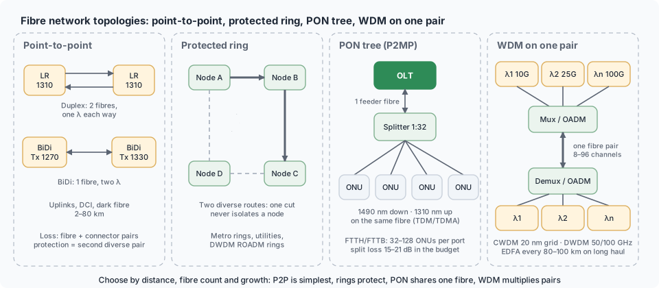
Basic topologies
| Topology | Structure | Fibres per link | Protection | Typical optics | Where |
|---|---|---|---|---|---|
| Point-to-point, duplex | A ↔ B on two fibres | 2 | none (or a second diverse pair) | SR/LR/ER, DAC/AOC | everywhere |
| Point-to-point, single-fibre BiDi | one fibre, two wavelengths | 1 | none | BiDi pairs (1310/1490, 1270/1330) | fibre-scarce routes, FTTx |
| Point-to-point WDM | N channels on one pair via mux/demux | 2 for N services | per system | CWDM/DWDM modules (CWDM, DWDM) | metro, campus interconnect |
| Star / hub-and-spoke | every site to a central node | 2 per spoke | dual-homing to two hubs | LR/ER by distance | campus, enterprise WAN |
| Ring | nodes in a loop, traffic both ways | 2 (single ring) or 4 (dual) | inherent: second path | LR/ER, DWDM with OADMs | metro, carrier access, utilities |
| Tree (PON) | one OLT fibre split 1:32–1:128 to ONUs | 1 feeder, 1 per subscriber | Type B/C protection optional | PON optics classes (How PON works) | FTTH |
| Mesh | many-to-many | many | rerouting | ROADM/coherent | core transport |
| Leaf–spine (folded Clos) | every leaf to every spine | 2 per link | multipath by design | SR4/DR4/AOC (Roles & topologies) | data centre |
| Bus / linear add-drop | nodes along one route | 2 | none | OADM | pipelines, railways |
Structured cabling hierarchy (TIA-568 / ISO 11801)
| Element | Role | Fibre choice | Notes |
|---|---|---|---|
| Entrance facility | where carrier cables enter; transition outdoor → indoor | as carrier | outdoor cable may run ≤ 15 m indoors unless rated (NEC 770) |
| Equipment room / main cross-connect (MC) | core switches, ODF | OS2 | all backbones terminate here |
| Backbone (vertical / campus) | MC ↔ intermediate (IC) ↔ horizontal cross-connects (HC) | OS2 (OM4 for short intra-building) | ≤ 2 000 m campus SMF; 12–48 fibres per closet typical |
| Telecommunications room (TR/HC) | floor distribution | — | access switches |
| Horizontal cabling | TR → work area outlet, ≤ 90 m | copper mostly; fibre in centralized cabling (≤ 300 m OM3/OM4) | fibre-to-the-desk rare but exists |
| Data centre (TIA-942) | MDA → IDA → HDA → EDA (ZDA optional) | OM4/OS2 trunks with MPO | ToR, EoR, MoR patterns below |
Data-centre cabling patterns
| Pattern | Cabling | Optics |
|---|---|---|
| Top-of-rack (ToR) | servers to a switch in the same rack over DAC; switch uplinks to spines over structured fibre | DAC ≤ 3 m; SR4/DR4/AOC uplinks |
| End-of-row / middle-of-row (EoR/MoR) | servers cabled across the row to a switch at the end/middle | AOC or SR optics 10–30 m; more fibre, fewer switches |
| Structured MPO trunks + cassettes | 12/24-fibre trunks between MDA and HDA/EDA, LC breakout in cassettes | any duplex optic; polarity method A/B/C (Breakout & MPO) |
| Direct point-to-point MPO | trunk straight between QSFP ports (SR4/DR4) | parallel optics; fewer connectors |
| Rail-optimised (AI) | each GPU NIC to a different leaf | AOC/DR4 mostly (Cabling an AI cluster) |
FTTx architectures
| Architecture | Fibre reaches | Last segment | Active equipment | Optics |
|---|---|---|---|---|
| FTTH — PON | the home | 1 fibre from splitter | OLT + ONU | GPON/XGS-PON classes; splitters 1:32–1:64 |
| FTTH — P2P Ethernet (AON) | the home | dedicated fibre per home | Ethernet switch + CPE | 1G/10G BiDi single-fibre |
| FTTB | the building | copper (Ethernet/VDSL/G.fast) inside | building switch/DSLAM | 1G/10G LR uplink |
| FTTC / FTTN | cabinet / node | VDSL over copper | street DSLAM | 1G/10G LR, CWDM |
| FTTA | the antenna | fibre to the RRU | RRU/AAU | 10/25G fronthaul optics (Fronthaul) |
| FTTx with WDM-PON / TWDM | the home | 1 fibre, wavelength per user/group | NG-PON2 | tunable ONU optics |
Split architecture in PON: centralized (one 1:64 splitter at the cabinet — flexible, one splice point) vs cascaded/distributed (1:4 then 1:16 along the street — less feeder fibre, more closures, ~0.5 dB extra) (ODN classes).
Fibre-count planning
| Rule | Reasoning |
|---|---|
| 2 fibres per duplex service, 1 per BiDi/PON subscriber | baseline |
| Add 50–100 % spare on backbone routes | civil works cost dwarfs fibre cost; pulling later costs more |
| Never fewer than 12 fibres in any outdoor cable; 24–48 between buildings; 96–288 on metro trunks; 864+ on ducts feeding data centres | granularity of splicing and ribbon counts |
| Plan WDM instead of fibres where duct space is the constraint | 8–96 services on one pair |
| Separate fibres (or cables) for protection paths | a second pair in the same cable does not survive a dig-up |
| Reserve fibres for monitoring (RFTS) and future PON splitters | — |
| Dark fibre lease vs wavelength/Ethernet service | dark fibre: you choose optics, you manage the plant; managed wavelength: provider's optics rules |
Protection and diversity
| Scheme | How | Switch time | Fibre cost |
|---|---|---|---|
| Unprotected | one path | — | 1× |
| 1+1 | traffic sent on two diverse paths, receiver picks | < 50 ms | 2× |
| 1:1 / 1:N | standby path activated on failure | 50 ms–seconds | 2× or shared |
| Ring (ERPS G.8032, MPLS-TP, OTN, SNCP) | reroute the other way around the ring | < 50 ms | ring fibres |
| Mesh restoration | control plane finds a new path | seconds | shared spare capacity |
| PON Type B / C | redundant OLT port / trunk / full duplication | seconds | +1 feeder fibre |
| Dual-homing (LAG/MLAG/ECMP to two nodes) | L2/L3 multipath | sub-second | 2× access links (Forwarding basics) |
Diversity means physically separate routes: different ducts, different building entries, different street sides. Two cables in one trench share the excavator.
Latency
| Medium | Delay | Note |
|---|---|---|
| Standard fibre | ≈ 4.9 µs/km (n ≈ 1.47) | 100 km ≈ 0.5 ms one way |
| Hollow-core fibre | ≈ 3.3 µs/km | trading, HPC (Fibre types) |
| Copper / microwave / free space | ≈ 3.3 µs/km | microwave beats fibre on straight paths |
| Add per hop | switches 1–10 µs, routers 10–100 µs, FEC/DSP in 400G+ optics 100–300 ns, coherent DSP µs | equipment, not glass |
Documentation of a topology
Every fibre network needs: a route map (GIS), cable and fibre numbering, splice diagrams per closure, ODF port maps, cross-connect records, test results per fibre and a change log — kept current (Maintenance & restoration, Installation & routes).
In CodingBox
Topology decides the optics list: BiDi pairs for single-fibre spokes, PON classes for trees, CWDM/DWDM channels for shared pairs, parallel SR4/DR4 for MPO trunks. CodingBox verifies each delivered module against that list — wavelength, channel, PMD, power class — before it goes to the site (Check transceiver, Code database).
Keeping the topology knowable — identifier schemes, labels, splice schedules, GIS and records: Documentation & labelling; the boxes at the nodes of these topologies — transponders, ROADMs, OLTs, protection switches, media converters: Transport & access equipment.