 English
  Русский
  中文
中文  Español
  Deutsch
  Français
 Fibre-optic links: how light carries data
Every material in this documentation ends at the same place — a glass thread a tenth of a millimetre thick carrying pulses of infrared light. A fibre-optic communication link is the transmitter that makes the pulses, the fibre plant that carries them and the receiver that turns them back into bits, plus everything in between: connectors, patch panels, splices, splitters and filters. This section explains the physics and engineering behind that chain in the depth needed to design, test and troubleshoot a link — why light stays in the fibre, what weakens and smears it, how far a given optic can go, what the passive plant is made of, how it is measured and how it fails.
Why fibre
| Property | Fibre | Copper (twisted pair / twinax) | Consequence |
|---|---|---|---|
| Bandwidth × distance | THz of optical bandwidth; 10 km at 100G on one pair | 100 m at 10G (RJ45), 3 m at 100G (DAC) | fibre for anything beyond the rack |
| Attenuation | 0.2–0.35 dB/km (single-mode) | 10–20 dB per 100 m at 10G | kilometres without regeneration |
| Immunity | no EMI, no ground loops, no crosstalk | susceptible | fibre between buildings and in industrial sites |
| Size and weight | 250 µm coated fibre; 12-fibre cable ≈ 3 mm | 6–8 mm per pair | density in ducts and racks |
| Cost | cheap glass, expensive ends (transceivers) | cheap ends, expensive at speed | the transceiver is the cost centre |
| Handling | fragile endfaces, bend radius, cleanliness | tolerant | the training this section provides |
The chain
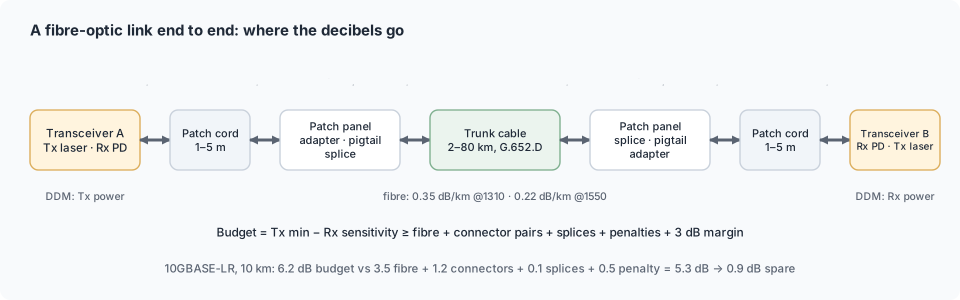
A link is a series of elements, each with a loss and some with a distortion:
- Transmitter — laser or VCSEL in the transceiver, launching −8 … +4 dBm of light at 850, 1310 or 1550 nm (Lasers).
- Patch cord — 1–5 m jumper from the module to a patch panel; two connector endfaces.
- Patch panel / ODF — adapter where the jumper meets a pigtail spliced to the cable.
- Cable — indoor, outdoor or hybrid, metres to tens of kilometres, one or hundreds of fibres (Passive plant).
- Splices, splitters, filters — fusion splices along the route; PON splitters or WDM muxes where the topology needs them.
- Far-end panel and patch cord — the mirror image.
- Receiver — photodiode in the far transceiver, needing −12 … −28 dBm depending on type (Receivers).
The link budget is the arithmetic that adds the losses of 2–6, compares them with the difference between 1 and 7, and leaves a margin (Link budget engineering).
The four things that limit a link
| Limit | What it is | Governs | Material |
|---|---|---|---|
| Attenuation | light lost per kilometre and per connector/splice | power budget, reach on single-mode | Attenuation & windows |
| Dispersion | pulses spreading in time until they overlap | reach on multi-mode; reach at 10G+ on single-mode at 1550 nm | Dispersion & bandwidth |
| Reflections and noise | back-reflections into the laser, receiver noise, crosstalk | penalties subtracted from the budget | Link budget engineering |
| Non-linear effects | at high launch powers in DWDM systems | amplified long-haul design | Non-linear effects |
Fibre in one paragraph
Light stays in the core because the core's refractive index is slightly higher than the cladding's — total internal reflection. A single-mode fibre (9 µm core) carries one path of light and reaches tens of kilometres; a multi-mode fibre (50 µm core) carries hundreds of paths that arrive at slightly different times, which limits it to hundreds of metres but lets it work with cheap 850 nm VCSELs. The details — modes, numerical aperture, bend loss, fibre grades OM1–OM5 and OS2 — are in How light propagates and Connectors & fibre types.
Generations of fibre links
| Era | Typical link | Enablers |
|---|---|---|
| 1980s | 850 nm LED on multi-mode, 10–100 Mb/s, < 2 km | first low-loss fibre, LEDs |
| 1990s | 1310 nm laser on single-mode, 155 Mb/s–2.5 Gb/s, 40 km; 1G Ethernet | DFB lasers, SC connectors |
| 2000s | 10G at 1310/1550, 80 km; DWDM 40 × 10G with EDFAs | WDM, amplifiers, SFP/XFP |
| 2010s | 40/100G parallel and WDM4; 100G coherent long-haul; PON to homes | VCSEL arrays, PAM4 start, coherent DSP |
| 2020s | 400G/800G PAM4 in the data centre, 400ZR coherent pluggables, 50G-PON | DSP in the module, silicon photonics |
The transceiver side of this history: What is a transceiver.
Further reading
- How light propagates in fibre — refractive index and total internal reflection, numerical aperture, modes, single- vs multi-mode, mode field diameter, cutoff wavelength, bend loss, fibre grades.
- Attenuation and transmission windows — Rayleigh scattering and absorption, the water peak, 850/1310/1550 nm windows, dB/km by fibre and wavelength, connector and splice losses.
- Dispersion and bandwidth — modal, chromatic and polarization-mode dispersion, bandwidth–distance product, dispersion-limited reach, compensation.
- Fibre types — ITU-T G.652–G.657 single-mode, OM1–OM5 multi-mode grades, specialty fibres, dissimilar-fibre joint losses, identifying installed fibre.
- Non-linear effects — SPM, XPM, FWM, Brillouin and Raman scattering, where they matter, optimum launch power, mitigation.
- Link budget engineering — the equation, loss allowances, penalties, margin policy, worked examples, receiver overload and attenuators.
- Passive plant — cables, patch panels, pigtails, splices, attenuators, splitters, WDM filters, enclosures and their loss allowances.
- Fibre network topologies — point-to-point, rings, meshes, PON trees, WDM; structured cabling, data-centre patterns, FTTx, fibre-count planning, protection.
- Cable routes and installation — ducts, direct burial, aerial, indoor pathways; bend and tension limits, route planning, closures, labelling, acceptance.
- Splicing and termination — the fusion splicing process, mechanical splices, pigtails and field connectors, acceptance criteria and defects.
- Testing and measurement — light source and power meter, OTDR, return loss, endface inspection, certification, using DDM as a meter.
- Fibre plant faults — bends, dirt, mismatches, bad splices, reflections, water: symptoms, signatures, fixes.
- Maintenance and restoration — preventive cycle, monitoring, spares, the restoration process, root causes of outages, plant lifecycle.
- Safety and handling — laser classes and hazard levels, live-fibre rules, glass and chemicals, site hazards, module and cord handling.
In CodingBox
The transceiver's DDM is the link's built-in power meter: launch power on one end, received power on the other, and the difference is the plant loss — which CodingBox reads on the bench and the switch reads in service (DDM in the app, Rx power & link budget).